The Engineering & Manufacturing Complexities of Injection Molding Automotive Barbed Hose Connectors
-
 By
Lee Lechner
 - Nov 4, 2020
The Engineering & Manufacturing Complexities of Injection Molding Automotive Barbed Hose Connectors
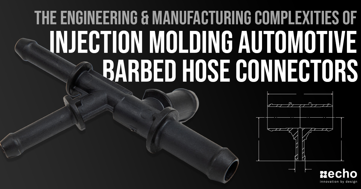
The burden of fluid connector part design and design for manufacturability has shifted from the OEM to the tier-1 supplier and their injection molding partner. Throughout this post, we’ll discuss what makes an injection-molded barbed connector technically complex, critical design elements that need to be factored in, and the molding expertise required to deliver a stable and repeatable part.
Early Recognition of Complicated Barbed Connector Designs Is Crucial
Some design elements can make a fluid connector very tricky to produce on time, on budget, and to spec. These include varying wall thicknesses, sharp transitions in geometry, small port sizes, and unreasonably tight tolerances/ GD&T specs.
The trick is to spot these early in the quote process, and a top-notch molding partner will do just that. Catching it early is critical because small changes to the part design can avoid headaches down the road. These headaches can include long PPAP timelines, high PPM rates, and asking the OEM for a deviation.
Injection Molding with Glass Filled Nylon 6/6
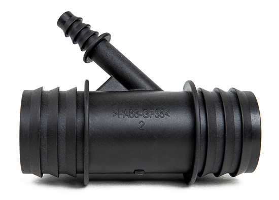
When you take a close look at nearly any automotive barbed connector, you'll notice that they're commonly 30%-35% glass-filled nylon (polyamide). Using glass fiber additives gives the material up to 80% more stiffness than regular nylon.
That said, glass fibers also make the injection molding process a little more complex. When glass-filled nylon is injected into the cavity, the glass fiber is lined up with each strand. As it nears obstructions, like core pins, it separates resulting in random angles, weakening the end product. Minimizing the number of turns will be vital towards minimizing and glass fiber filler risks.

Mold Shrinkage
When molten plastic is injected into the mold's cavity, the plastic shrinks as it cools and solidifies. In order to hit tight automotive specs, mold makers must have this factored in. When it comes to PA 66 GF 30%-35% for injection molding barbed hose connectors, you're typically going to see a shrinkage rate of approximately 0.2% - 0.6%.
Hose Barb Design
The connection between a connector and the tubing must be secure and reliable. With this post being focused on automotive applications, connectors can not afford to be the failure point that shuts down operations.
A critical element in designing an effective connector will be the barb. The hose barb is a bump/ridge on the connector used to grip the inside diameter of a tube to seal the connection.
There are three main design elements that need to be taken into consideration here:
- Barb's Outside Diameter (OD) - The OD of the barb(s) needs to be correlated to ID of the tube it will be attached too. When designing a connector, the accuracy of the tube's ID, material, tube flexibility, and application will be critical. For tighter seals where no clamp will be used, you'll need to increase the OD of the barb(s), but be careful as to not go overboard. If you do, installation could become your biggest bottle-neck.
- Sharp vs. Rounded Edges - Depending on the tube/hose material used, you'll need to develop a barb that is just sharp enough to grip/seal the tube, yet round enough as to not cut into the tube.
- Parting Line - We'll go into more detail later in this post, but the parting line is often overlooked when it comes to the design of connectors even though it plays a crucial role. Essentially, injection molding tools must be designed to avoid a parting line being on the end barb itself. This is critical towards creating an effective seal.

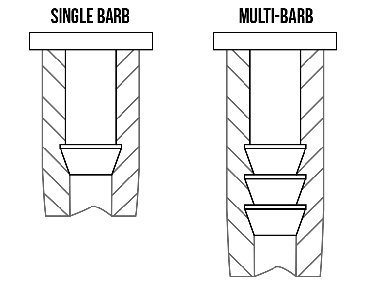
Single Barbed vs. Multi-Barbed Connectors
Because barbs are designed to grip the inside of a tube, it's easy for someone to assume that more barbs will provide a stronger hold and seal, but that's not usually the case.
If you're able to space out the barbs to allow the tubing being used to relax between the barbs, then the added barbs can actually be beneficial by providing additional grip. For the most part, though, you'll see more single barbed connectors, as the right design will achieve the necessary sealing requirements.
Another reason why you'll see more single barbed connectors has been due to the usage of clamps as a way of ensuring the hoses/tubes stay firmly on.

Parting Line Review
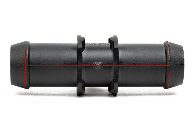
The parting line is the line of separation on the connector where the two halves of the plastic injection mold. This also means that it will determine the direction that the mold will open and the direction that the connector's features must be drafted for ejection.
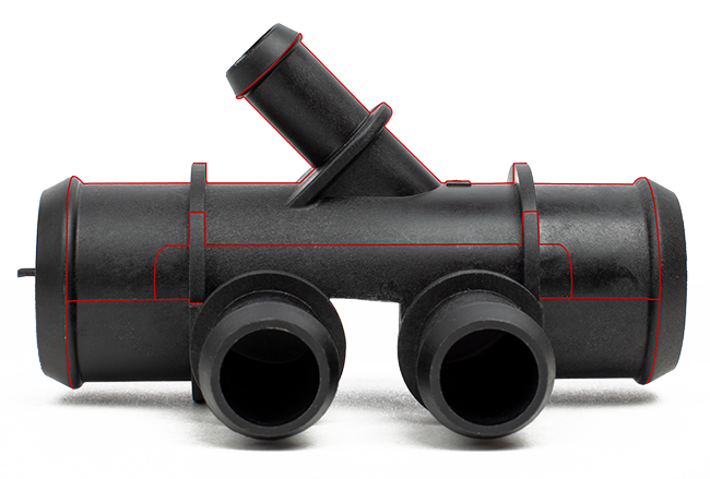
For most basic connectors, the parting line will simply be right down the middle. But, in many other cases, complex connectors will require a much more complex parting line design that requires experienced injection molders and tool designers.
As mentioned earlier, the outside barbs must remain free of a parting line that goes to the end, as a parting line on the barb would most likely result in leakage. With advanced molding processes, a mold can be designed to take the parting up to the base of the barb, allowing the barb to have a uniform surface with no parting line.
Central Connector Parting Line

Complex Connector Parting Line

Gate Location & Design
The gate location is where the molten plastic is going to be injected and forced into the cavity. It's an extremely critical element towards the success of a complex barbed connector.
When determining where the gate location should be, injection molders will typically look to place it at the deepest cross-section in order to give it the best flow that will help minimize voids and sinking. A poorly placed gate will result in the plastic resin 'freezing' off before hitting critical areas.
The design/size of the gate is also going to play a major role in the injection molding process, and it's commonly overlooked when it comes to these components. In order to meet tight barbed connector specs, injection molders make the gate slightly larger in order to ensure molten plastic is injected fast enough to avoid part warpage and flaws.
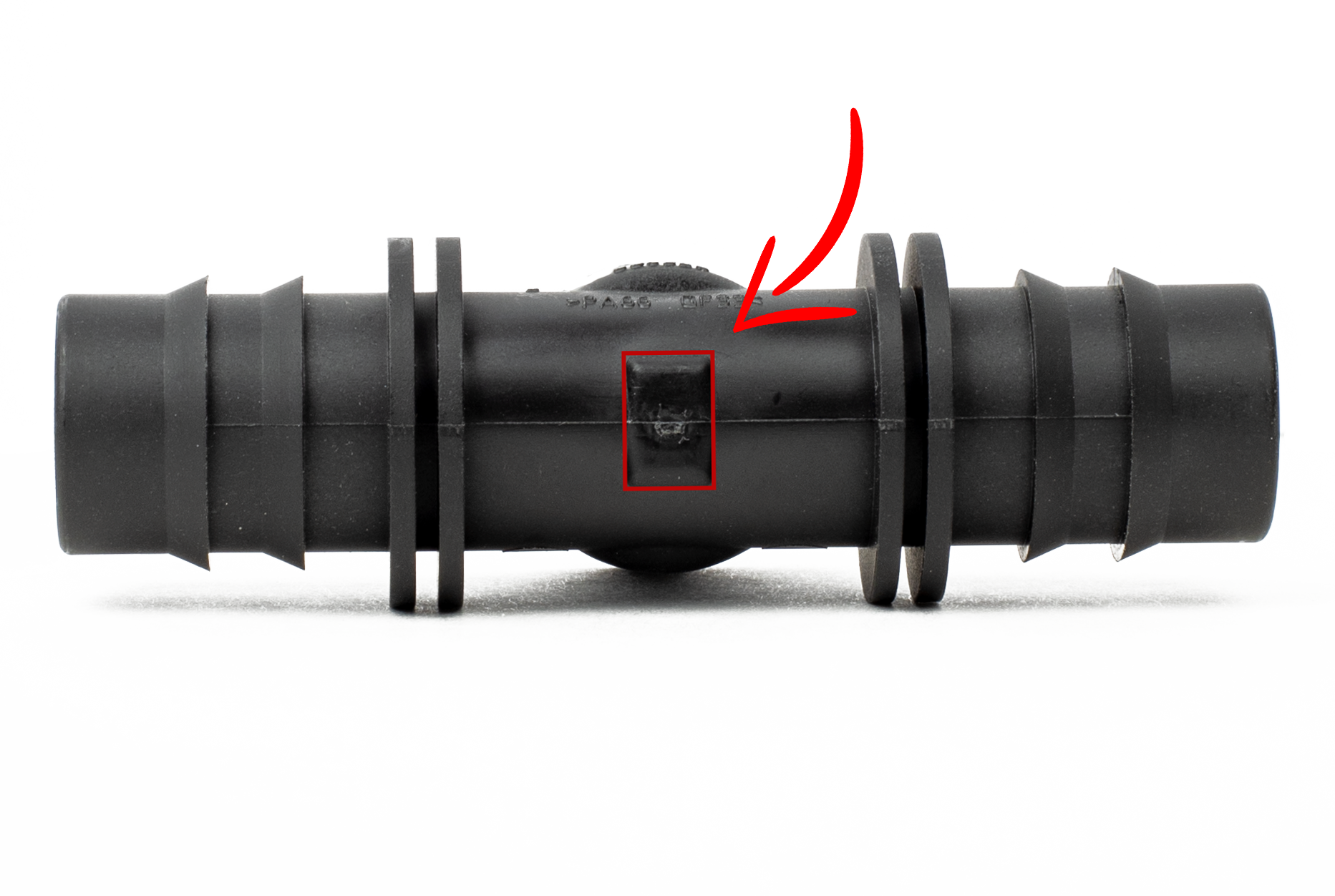

Ejector Pin Location Review
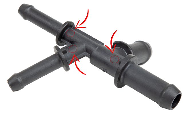
Creating an effective seal is crucial towards the success of an automotive barbed connector. In order to achieve this in regards to the mold design related to the barbs, you need to factor in ejector pins locations.
One of your goals when selecting ejector pin locations is to minimize the effect they'll have on the part. When it comes to connectors, ejector pins can not be located on vital areas, such as the connector's barbs.
Mold engineers also need to under the difference between a complex design vs. simple designs, as the complex structures typically require more ejection force. Because of this, you'll need to find to balance it via increasing the number of ejector pins accordingly.

Injection Molding Tool Design Can Offset Complex Geometries
Injection molding is a dance between quality, cycle time, and cost. All three are tightly wound together. Experienced tool designers and molding partners will tell you that it’s really tricky to produce round parts. It looks easy but plays hard. This is because residual stresses in the part can make it challenging to hit the specs, leading to longer cycle times to let the part cool, increasing the cost.
Residual stresses can warp round parts (like barbed connectors) after they are released from the mold. This can be offset by exotic materials and longer cooling cycles, but that also drives up cost.
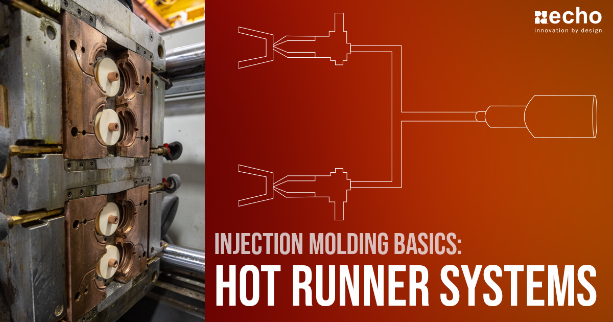
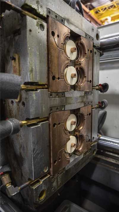
Quality tool engineers can balance melt flow and reduce cycle times with hot runner systems, increase cooling capacity with copper cores and forced air flows, and produce precise round parts with out-of-round tools (what??). Yes, you read that correctly.
Depending on the part design, material flow, and residual stresses, sometimes it takes an out-of-round tool to produce precision round parts like fluid connectors. Molding partners that don’t know this can set themselves and their customers up for a very long and hard journey.

Design Responsibilities Shifts to the Tier-1 Suppliers
Engineering resources at automotive OEMs have shifted away from “classic” part design and toward strategic priorities, such as electrification. As a result, the burden of part design and design for manufacturability is falling more and more to you—the tier 1 supplier—and your injection molding partner. Since so much production has gone to low-cost countries it’s even harder to find a molding partner with local expertise in part design, tool design, and processing.
Finding the Right Injection Molding Partner
If getting the fluid connector done right is your primary driver, then make sure you choose the right molding supplier. If they aren’t asking you lots of questions about wall thicknesses, sharp transitions, knife edges, tolerances & technical specs, gate locations, and materials, then they probably are not doing in-depth part feasibility upfront. That should send off warning bells.
Ammex (an Echo Company) has been tooling up and supplying hose connectors for 20 years, has shipped millions of parts, and runs at a PPM rate of <2. If you’re looking for a new or alternate molding partner, let us know below and we’ll get back to you ASAP.


