
Recommended File Formats for Sharing CAD Designs
-
 By
Lee Lechner
By
Lee Lechner - May 19, 2020
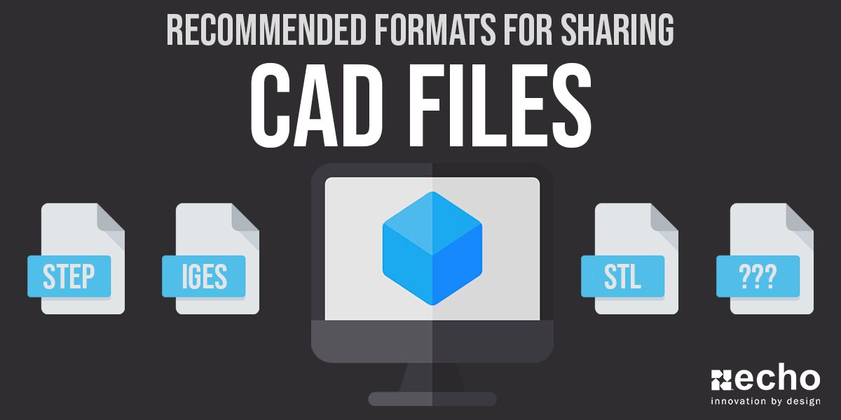
Recommended Formats For Sharing CAD Files
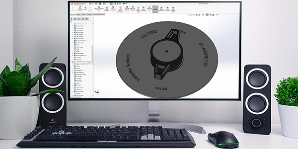
Whether you're looking to get a part produced, quoted, modified, 3D printed, etc., it's important you understand the different types of CAD file formats and which one you should use. CAD files are extremely important starting at design conception all the way to production and quality inspection.
Unfortunately, because of the variety of different CAD Softwares available today, file compatibility has become a major issue. Because of this, you'll need to learn the difference between native and neutral CAD file formats.
For Skimmers:
- Quick Post Preview: In this post, we cover the different CAD file formats & extensions, their Pros & Cons, and which format you should choose.
- Who This Post Is For: Engineers, Purchasers (who typically deal with quoting projects), Program Managers, Architects, Designers, Students, and anyone else who uses CAD software.
- Approximate Post Read Time: 5 Minutes
Native File Formats
Native file formats are based on the particular CAD software you're using, giving you access to the most information possible about your CAD file. Native files give you the ability to take full advantage of all the features of a specific program (like SolidWorks), instead of skipping over aspects like what you'll see later with the neutral file format. Because of this, if your customer or vendor has the same CAD software as you, we recommend sticking with the native format.
I'm not going to go into full detail about these, but I wanted to at the very least list out the most common native CAD file formats you'll see:
| Format | Extensions |
| AutoCAD | .dwg |
| CATIA V4 | .model |
| CATIA V5, V6 | CATPart, CATProduct, CGR |
| Creo | .prt, .asm |
| NX, Unigraphics | .prt, .jt, .j_t |
| Pro/E | .prt, .asm |
| Inventor | ipt, iam |
| MicroStation | dgn |
| SolidWorks | .sldprt, .sldasm |
| Solid Edge | .par, .asm, .psm |
Neutral File Formats
Neutral file formats were developed to make it easier to exchange files with someone that is using different CAD software. These types of file formats are extremely beneficial when you don't want to pay for another CAD software you may only use once or twice. The major drawback of choosing a neutral format is typically data quality degradation.
The most common neutral file formats we'll be going in-depth on include:
| Format | Extensions |
| STEP | .stp, .step |
| STL | .stl |
| IGES | .igs, .iges |
| 3D PDF | |
| Parasolid | .x_t, .x_b |
| VRML | .vrml |
| X3D | .x3d |
| COLLADA | .dae |
| DXF | .dxf |
STEP (.stp, .step)
STEP is the most popular neutral CAD format in the world today as it was standardized by ISO committee in 1994 under the official name “ISO 10303-21", and was designed to be the international standard. STEP stands for STandard for the Exchange of Product model data.
Pros
- Stores data using a mathematical representation of curves (referred to as NURBS) to give a perfect surface definition
- Most widely used and accepted neutral format today (standard across many industries)
- Developed by ISO
- Good file compression (making it more ideal for sharing over the internet)
- No loss of quality with the source files in terms of details
- Allows downward compatibility (Example: A file created in Autodesk Inventor 2016 can still be used in Autodesk Inventor 2015)
Cons
- No materials or textures as STEP focuses on shape and form
- Slow to release new updates quickly
- No lighting or camera data
- Can't be directly rendered as it needs to be processed by a software algorithm that converts the mathematical surface representation into a series of triangles
- Cannot contain parametric intelligence and feature history
STL (.stl)
STL, which stands for Sterolighography, was designed back in the 80's when file size was a BIG deal. Similarly, it is only been within the last decade that the "model is master" has been adopted by the industry. The STL file was built in a time where things like texture, small details, and EVERYTHING you ever wanted to know about a part was captured in the drawing, not the CAD file. The CAD file, up until recently, was supplementary. But now, you can store measurements, material information, texture, and loads of other information about the part.
So why do we use stuff like STLs today? Well, it's easy. The code is written. It's inexpensive to continue to use something that's been around for so long. And it still has its value today. Again, great for rapid prototyping and small file size.
Pros
- Great for prototyping or gathering estimated volumes and measurements from
- Nearly universal and very commonly used
- File size
Cons
- Not something you'll want to use if you were going to need super-precise measurements. It is not a precise representation of a part
- Geometry resolution can cause issues in manufacturing (a circle will never be a true circle)
- Only describes the surface geometry of a 3D object
- Does not represent Color, Texture, or other common CAD Attributes
IGES (.IGS, .IGES)
IGES, which stands for Initial Graphics Exchange Specification, was the first neutral CAD file format invented towards the late 1970s, early 1980s. This format is mainly used for surface geometry and design work. While IGES is widely supported, it has a hard time computing complex parts' faces, so it will guess and break models into surfaces, resulting in the user having to repair to get to solid body in some instances. Its limitations and the variety of better alternative neutral formats are resulting in engineers moving away from this file type.
Pros
- Widely supported
Cons
- Files are imported as solid models, not surface geometry
- Often gets translated with gaps between the surfaces, missing faces, and occasionally surfaces with faces in the wrong orientation
- Cannot carry MBD (Model-Based Definition) data, nor can it carry PMI (Product and Manufacturing Information) data
- IGES files often have to be repaired resulting in engineers having to spend several hours a week fixing design data
3D PDF (.pdf)
3D PDF format is considered as more of a universal choice for sharing and exchaging CAD prints as anyone with Adobe Reader can open and view it.
Pros
- Easily viewable on computers, smartphones, and tablets
- Great for sharing with those who don't have CAD software or viewers, as PDFs only require Adobe Reader to view files
- Can be used to help reduce file size in order to send via email
Cons
- Slow performance
- Very limited capabilities
Parasolid (.x_t, .x_b)
Parasolid is a geometric modeling kernel that can be licensed by other companies for use in their CAD software. This format's capabilities include model creation and editing utilities, advanced surfacing, thickening & hollowing, blending & filleting, and sheet modeling.
Pros
- Great CAD export option for engineers using SolidWorks or NX
Cons
- Not a standard format
- Cannot communicate and migrate 2D data such as lines and arcs
- Has to be licensed
VRML (.vrml)
VRML, which stands for Virtual Reality Modeling Language, is a standard format used to represent 3D interactive vector graphics. VRML files are in plain text and are useful for transferring over the internet more quickly. This format uses a polygonal mesh to encode surface geometry & can store appearance-related information (such as color and texture).
Pros
- Compress well using gzip, making it more useful for transferring via the internet
Cons
- Failed to gain traction due to capabilities remaining stagnant while 3D graphics improved quickly
X3D (.x3d)
X3D was the successor of the VRML format. X3D is an XML based 3D file format that supports all features of the XRML format, along with some additions. For example, on top of being able to store appearance related information (like what you can dow with VRML), X3D adds NURBS encoding of the surface geometry, the capability of storing scene related information, and support for animation.
Pros
- Designed to integrate seamlessly with HTML5 pages (wants to become the standard 3D file format for the web).
Cons
- Has not received wide acceptance
COLLADA (.dae)
Collada is a 3D file format used more heavily within the video game and film industry. This format supports geometry, appearance-related properties, materials, textures, and animations. In 2013, it was adopted by ISO as a publicly available specification, ISO/PAS 17506, which resulted in lots of 3D modeling software supporting the format
Pros
- Supports kinematics and physics
- Supported by lots of 3D modeling software
Cons
- Hasn't stayed up to date, resulting in some shifting more towards other formats
DXF (.dxf)
DXF, whicch stands for Drawing eXchange Format, is the neutral format from AutoCAD that can cross platforms (unlike the DWG format). DXF is a vector file that stores 2D drawings, meaning that you can edit individual elements that make up an image. DXF files are widely used as DWG since it is supported by most CAD programs.
Pros
- Open-sourced and almost every CAD software supports it
Cons
- DXF files are usually larger in size
- Only retains information such as line work, dimensions, and text
- Does not support application-specific information
What Format Should I Use?
All of this information about CAD file formats for sharing engineering design is all fine and dandy, but for those of you looking for quick answers to common questions, check out what we recommend below:
Best Results and Data Quality
Use a Native CAD format as long as both you and your customer or vendor have the same CAD software that you're using.
Best Neutral CAD Format Option
At Echo, our preference goes to STEP format as it is the most popular neutral CAD format in the world. With that said, it may come down to the project you're working on. If your file contains texture or material, the STEP file may not be your best option.
3D Printed Parts / Rapid Prototypes
STL format is an excellent choice for this option.
You May Also Like...